
Safety & protectionARD-SF-004
Connection optionsCryogenic safety valve
Male BSP/NPT
A spring-loaded pressure-relief valve with male threaded catalogue connections. DN10, DN15 and DN25 are listed; set pressure and certified relieving capacity are selected separately.
- Size
- DN 10–25
- Body material
- CF8
- Connections
- Male BSP / NPT threaded
- Operation
- Spring-loaded pressure relief
- Pressure
- Set pressure to specify
- Temperature
- −196 to +80°C · series*
Engineered for your application
A spring-loaded pressure-relief valve with male threaded catalogue connections. DN10, DN15 and DN25 are listed; set pressure and certified relieving capacity are selected separately.
Sizes and pressure ratings depend on construction, materials and configuration. Confirm the selected pressure-temperature rating with the quotation.
Technical data
The specification, in detail.
| Parameter | Technical specification |
|---|---|
| Size range | DN 10–25 |
| Pressure ratings | Set pressure to specify |
| Connection | Male threaded, BSP / NPT |
| Pressure / setting | Specify rating and required set pressure |
| Operation | Spring-loaded pressure relief |
| series temperature* | -196°C to +80°C |
| Medium | LNG, LOX, LN2, LAr, CO2 |
Nominal pressure and ASME class are different rating systems. Confirm the pressure–temperature rating for the selected material and design.
End connections
Define the interface.
Shown configuration: Silver spring housing, brass-coloured cap and lower fitting, male side outlet and male downward adapter.
| Connection detail | Connection / selection requirement |
|---|---|
| Published connection | BSP · NPT · Male |
| Thread standard | BSP and NPT are separate options. Confirm exact designation, taper/parallel form and male/female inlet and outlet; metric reference threads must not be relabelled as BSP or NPT. |
| Reference drawing scope | PN40 reference relief arrangement with metric M1/M2 connections, DN10, DN15 and DN25. BSP/NPT variants need their own drawings. Spring bands are listed separately; certified discharge capacity is required for sizing. |
The illustration shows one configuration. Published connection alternatives are options for enquiry; their availability depends on size, rating, material and design. Installation dimensions come from the drawing, not the illustration.
Materials
From body to seal.
| Component | Material / option |
|---|---|
| Body | CF8 |
| Seat | HPb59-1 |
| Disc | HPb59-1 |
Supplied reference arrangement
Materials apply to the supplied reference arrangement. PN40 reference relief arrangement with metric M1/M2 connections, DN10, DN15 and DN25. BSP/NPT variants need their own drawings. Spring bands are listed separately; certified discharge capacity is required for sizing.
| Component | Reference arrangement material |
|---|---|
| Dust Cover | HPb59-1 |
| Bonnet | CF8 |
| Disc | HPb59-1 |
| Upper Gasket | T2 |
| Stem | HPb59-1 |
| Gasket | PTFE+C |
| Lock Nut | HPb59-1 |
| Spring Bottom Pad | HPb59-1 |
| Body | CF8 |
| Adjusting Nut | HPb59-1 |
| Sealing | T2 |
| Valve Seat | HPb59-1 |
| Spring | S30210 |
| Gland Ring | HPb59-1 |
Published material alternatives are configuration-dependent. H.F. denotes hard facing; the exact grade and material certificates are confirmed with the offer.
Selection notes
Defined around your application.
- Catalogue body: CF8
- Published connections: BSP · NPT · Male
| Engineering data | Configuration requirement |
|---|---|
| Dimension data | Reference table and drawing: DN10, DN15, DN25. Dimensions and connection reference. |
| Installation drawing | Confirm BSP or NPT, male/female ends, thread sizes, engagement, end-to-end length and installation clearance. |
| Pressure-temperature rating | Confirm allowable inlet pressure at the relieving temperature for the selected body, trim and seals. Specify set pressure, back pressure and certified relief capacity separately. |
Sizes and pressure ratings depend on construction, materials and configuration. Confirm the selected pressure-temperature rating with the quotation.
*−196 to +80°C is the series/reference range. It does not establish the allowable pressure at each temperature or suitability of every seat, seal and actuator. Confirm the selected assembly’s minimum design temperature and pressure–temperature curve.
Specify required set pressure, relieving medium and temperature, back pressure and certified capacity. Spring-setting bands, nominal pressure and flange rating are separate values. No capacity or approval is inferred from the product illustration.
Catalogue construction and supplied reference-arrangement materials are shown separately below the material schedule. Use the approved drawing for the quoted body, trim and connections.
Published ratings do not establish suitability for every listed medium. Oxygen cleaning, material compatibility, trapped-liquid relief and project approvals are specified for the selected assembly. Liquid-hydrogen and helium service require a separate temperature and material review.
Arden product datasheet
Product code ARD-SF-004 · Revision 2026-10-28. Product illustrations show one configuration; the approved order documentation defines the supplied assembly.
Download PDFDimensions
Plan the connection.
Dimensions apply to the tabulated version only. Confirm the approved outline drawing for the selected size, rating and connections before installation.
PN40 reference relief arrangement with metric M1/M2 connections, DN10, DN15 and DN25. BSP/NPT variants need their own drawings. Spring bands are listed separately; certified discharge capacity is required for sizing.
Dimensions and connection reference
| DN | H | H1 | D0 | L | M1 | M2 | Set pressure (MPa) | Weight (kg) |
|---|---|---|---|---|---|---|---|---|
| 10 | 161 | 56 | Ø10.5 | 49 | M30x1.5 | M36x2 | 0.4 - 1.59 | 0.8 |
| 10 | 161 | 56 | Ø10.5 | 49 | M30x1.5 | M36x2 | 1.60 - 2.7 | 0.8 |
| 10 | 161 | 56 | Ø10.5 | 49 | M30x1.5 | M36x2 | 2.71 - 3.5 | 0.8 |
| 15 | 161 | 56 | Ø10.5 | 49 | M30x1.5 | M36x2 | 0.4 - 1.59 | 1.0 |
| 15 | 161 | 56 | Ø10.5 | 49 | M30x1.5 | M36x2 | 1.60 - 2.7 | 1.0 |
| 15 | 161 | 56 | Ø10.5 | 49 | M30x1.5 | M36x2 | 2.71 - 3.5 | 1.0 |
| 25 | 186 | 69.5 | Ø15 | 63 | M36x2 | M45x2 | 0.4 - 1.59 | 1.5 |
| 25 | 186 | 69.5 | Ø15 | 63 | M36x2 | M45x2 | 1.60 - 2.7 | 1.5 |
| 25 | 186 | 69.5 | Ø15 | 63 | M36x2 | M45x2 | 2.71 - 3.5 | 1.5 |
Linear dimensions are in mm and weights in kg unless stated otherwise. Pressure bands in MPa, thread designations and ISO mounting codes are not linear dimensions. Thread designations follow the reference. An em dash means no value is published. Confirm a certified outline drawing for the selected configuration.
Documentation
Product documents
Download the Arden data sheet for ARD-SF-004, or request the outline drawing for your selected configuration.
Product code ARD-SF-004 · Revision 2026-10-28. Illustrations show one configuration; approved order documentation defines the supplied assembly.
Explore the range
Another configuration?
 Safety & protection
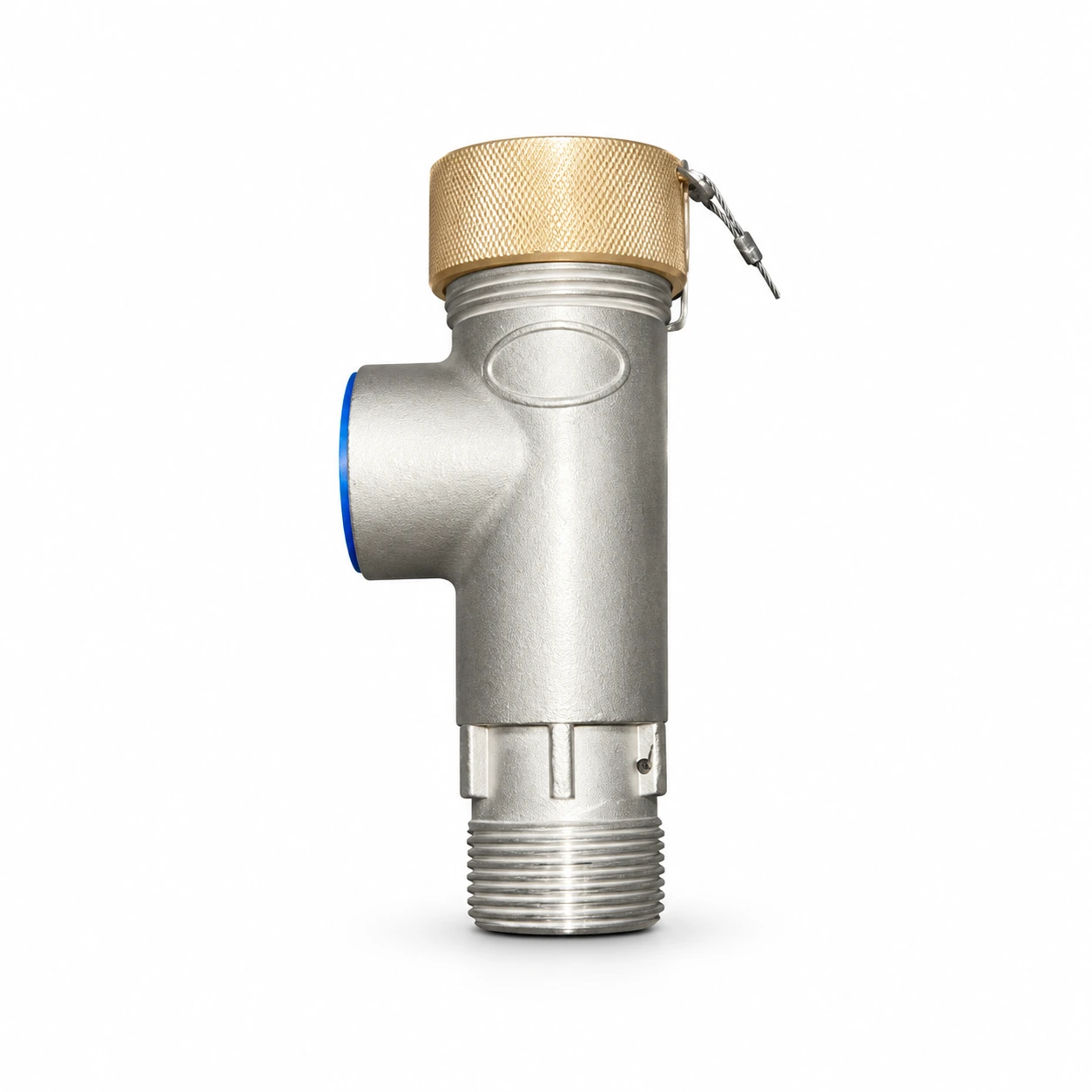
ARD-SF-001
Low-lift safety valve
- Size range
- DN 10–40
- Pressure ratings
- PN40 (4.0 MPa nominal)
- Temperature
- −196 to +80°C
- Connections
- Threaded / union
- Medium
- O2, N2, Ar, CO2, NG
 Safety & protection
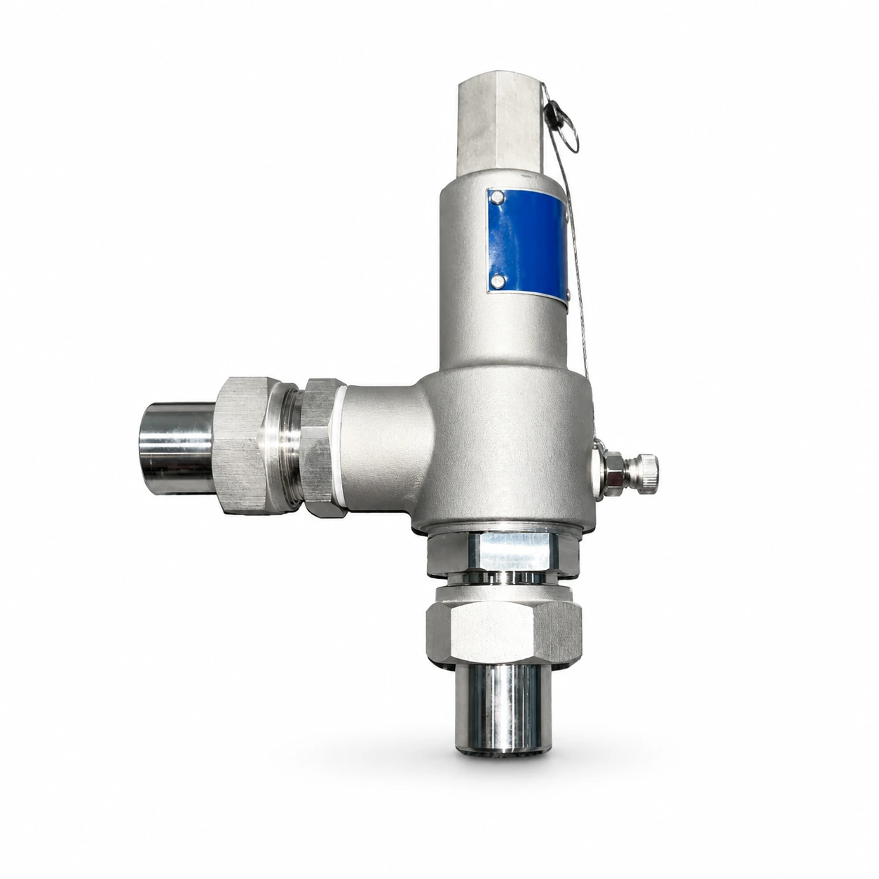
ARD-SF-002
Full-lift safety valve
- Size range
- DN 10–40
- Pressure ratings
- PN40 (4.0 MPa nominal)
- Temperature
- −196 to +80°C
- Connections
- Threaded / union
- Medium
- O2, N2, Ar, CO2, NG
 Safety & protection
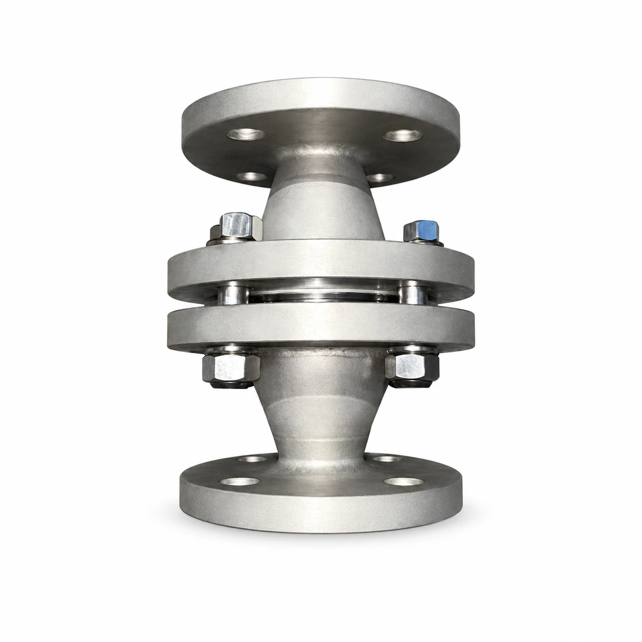
ARD-SF-003
Flanged flame arrester
- Size range
- DN 25–250
- Pressure ratings
- PN16 (1.6 MPa nominal)
- Temperature
- −196 to +60°C
- Connections
- Flanged